The AU Library:
Fields and Cameras
Andrew Glassnerhttps://The Imaginary Institute
15 October 2014
andrew@imaginary-institute.com
https://www.imaginary-institute.com
http://www.glassner.com
@AndrewGlassner
Imaginary Institute Tech Note #7
Table of Contents
- Introduction
- AUField
- AUMultiField
- Cameras and Motion Blur
- Shutters
- The AUCamera
- Debugging
- Custom Shutters
- A Comment About Moving Shutters
- Examples
- Resources
Introduction
In this note, I will discuss two distinct ideas that are related only circumstantially. The first I call fields, the second, cameras. These are both part of my AU (Andrews Utilities) library for Processing.
Before we start, a quick note on the word "field" to prevent any confusion later on. The problem is that this word already has multiple meanings in different disciplines. To a mathematician, a field is a collection of objects and operators that has specific properties. To a physicist, a field is a physical value that can be measured at every point in space. To many computer graphics people, a field is a two-dimensional grid of floating-point values, like a height field, where the value at each entry gives us the elevation of a terrain at that point. Since I'm a computer graphics guy, that's how I use the word here.
The cameras we'll talk about are directly modeled on physical cameras, and contain idealized versions of a cameras shutter and film.
You might think that though cameras could be cool, the fields are unnecessary, since Processing already offers a 2D array of values: the onscreen pixel array itself (or even a PGraphics object containing off-screen pixels). That's true, but those structures are limited to storing only 8-bit integers (albeit three of them at each pixel). So they are useless if our goal is to store arbitrary floating-point numbers. But worse, being limited to only small integers creates a ton of problems.
Here's one such problem that directly affects building things like cameras, the other topic of this note. Suppose you want to combine 100 black-and-white pictures into one by simply averaging them together. You might just add them all up and then divide by 100. But just adding them up doesn't work right. Suppose the upper-left pixel in every image has the value of 255 (remember, were working just with grayscale pictures at the moment). When you've added the images together, that pixel isn't (100*255), but just 255, because that's the biggest value you can store.
That's a bummer. So to compensate, before you add each image to the running sum, you multiply every pixels gray value by 1/100.
But because were working with integers, you end up with only four values of gray! The value 255 goes to 3, the value 0 goes to 0, and all your intermediate shades of gray go to values 1 and 2. Below on the left is a picture Id like to add to my sum. I scaled the picture by 1/100, and added it to itself 100 times. The result is on the right. Notice that weve posterized, or quantized our wonderful smooth grayscale picture to just black, white, light gray, and dark gray. Weve lost a ton of detail just about everywhere and the result doesn't look much like our original. This is clearly not a good result.
This problem goes away if we use floating-point numbers for our values. Then we can multiply them all by 1/100.0 and add them up, and the result will look just like the original (floating-point numbers arent perfectly accurate, of course, but in everyday use the very tiny inaccuracies are rarely visible).
The AU (Andrews Utility) library offers two kinds of fields: one stores a single float at every position, the other stores three. The first version is useful for anything that needs just a single value at each pixel. The second version is intended for holding color images, but you can use it for anything else that needs 2 or 3 values per pixel.
The camera objects offered by the AU library is primarily designed to help with the creation of motion-blurred animations. You create multiple images for every output frame, and the camera combines these with your choice of shutter to create a single, motion-blurred frame. Using the camera is easy, but there's lots of flexibility.
AUField
As I discussed above, a generic field is merely a 2D grid of floats. My implementation of this idea is named an AUField. I've made this a more useful object by including a bunch of routines that manipulate those values in handy ways.
Since there's not much theory behind fields, lets jump right into the mechanics.
Creating
To create a field, you call the constructor with a pointer to your sketch (simply use the keyword this ), along with the width and height:
AUField(PApplet app, int wid, int hgt);
For example, to create your own field you could write:
AUField myField = new AUField(this, fieldWidth, fieldHeight);
Using the system variables width and height will create a new field with the same dimensions as your graphics window. Though matching the size of your graphics window is very common, you can make your field any size you like.
Your new field starts out with a value of 0 at every location.
Fields are meant for you to freely get into and manipulate directly (they're not like typical opaque objects in object-oriented programming, where all the internal details are hidden). Fields have three internal variables that you can freely access:
- int w: the width (read-only; don't assign to this variable!)
- int h: the height (read-only; don't assign to this variable!)
- float[] z: the 2D array of values (read and write these freely)
Important! Read this! The variables w and h pop up all the time when you're writing loops to read and write values. Because the're so handy and used so frequently, I've chosen to give you direct access to these. You must never write to them, but there's no sensible way for me toprevent it. So never change w or h! The library will assign to these the right values when you make your field. From then on, you can read them all you like, just never change them. Of course, you can read and write the contents of z with abandon. Just never change w or h! If you do, your program could very likely crash. If you want to change the size of your field, make a new one.
To read or write into the z field, you first specify the y location and then the x . For example, if you had a field named myField , and you want to take the value at x=3, y=5 and put it into x=8, y=2 , you'd write
myField.z[2][8] = myField.z[5][3];
Remember that the indices are y first, then x. As usual, both indices start counting at 0.
Once you have your field, there are a bunch of things you can do with it.
Reading and Writing
You can copy the pixels from the screen into a field, or copy a field back to the screen. Since a field can hold only one value per pixel, you can control how your RGB pixels are turned into single numbers (in Section 3 we'll see another field designed for color images and transparency). Your choices are:
- FIELD_RED: Save just the red value.
- FIELD_GREEN: Save just the green value.
- FIELD_BLUE: Save just the blue value.
- FIELD_AVG_RGB: Save the average of red, green, and blue
- FIELD_LUM: Save the luminance (.3*red + .59*green + .11*blue)
If your pixels are in shades of gray, then these will all return the save value.
Here's the call to fill up an AUField from the current graphics windows pixels:
void fromPixels(int valueType);
where valueType is drawn from the list of 5 options above.
For example, to make a field and then fill it up with a grayscale version of whats on the screen, you could say
This will make the field (you only need to do this once), and then it will save the luminance of each on-screen pixel.
To draw your field on the screen, just tell it where to put the upper-left corner:
void toPixels(float dx, float dy);
Here each field entry becomes a gray pixel, so if you've changed the fields contents, you'll probably want to make sure your field has values in the range of 0-255. Any values below 0 will be turned into 0, and any values above 255 will become 255.
Sometimes you'd like to copy only some of the pixels from your field. You can control this with a mask, which tells the system how much each fields pixel should contribute to the final value. Masking lets you easily create images that would otherwise be hard to make.
For example, lets draw a set of vertical stripes, but only inside a circle, on a red background, as in this figure:
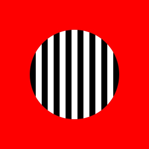
Creating this involves three images. Let's call the red background simply the background, the stripes the stripes, and the circular mask the mask. The general idea is that we work our way through the picture, one pixel at a time. We then get the corresponding values from the pixels of the mask and background. The mask tells us how to combine the picture and the background on a pixel-by-pixel basis.
When the mask is white (value 255), it means replace the background color with the fields color. When the mask is black (value 0), it means leave the background untouched. Values between 0 and 1 give us intermediate degrees of blending.
Here are the background, the picture, and the mask for the above image.
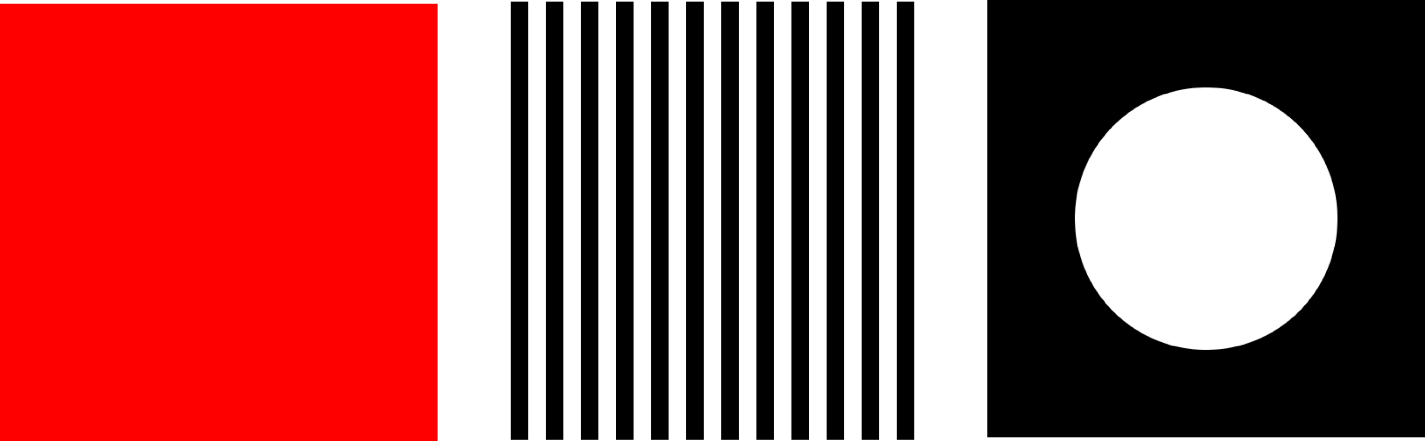
I used a simple geometric shape for my mask, but a mask can be anything you want. It can even be a grayscale version of a photograph. The library simply reads each pixel and treats it as a blending control, from don't draw the picture color at all (mask black, value 0) to replace the screen pixel with the picture color (mask white, value 255), and everything in-between.
To draw with a mask, you only need to provide the mask as another argument to toPixels(). The mask is just another AUField:
void toPixels(float dx, float dy, AUField mask);
In this call, the upper-left corner of the mask sits on the upper-left corner of the picture. Its often useful to move the mask with respect to the picture. You can do that by providing two values that give the upper-left corner of the mask relative to the upper-left corner of the picture.
void toPixels(float dx, float dy, AUField mask, float mx, float my);
You can write your field into an offscreen PGraphics object instead of the onscreen pixels, if you want. It should be the same size as your field. To do this, simply provide the PGraphics object at the end of the parameter list to the appropriate form of toPixels(). There are three versions, one for each flavor of toPixels() we saw above.
void toPixels(float dx, float dy, PGraphics pg);
void toPixels(float dx, float dy, AUField mask, PGraphics pg);
void toPixels(float dx, float dy, AUField mask, float mx, float my, PGraphics pg);
Important note! There's an really good reason for sometimes preferring to use a PGraphics object rather than directly drawing to the screen. For efficiency reasons, toPixels() is not affected by Processing's transformations commands (like translate(), scale(), and rotate()). No matter what transformations you might use, toPixels() will always draw the field with rows running left-right and columns running up-down. Your only control over this is to move the upper-left corner with the first two parameters to toPixels(). If I didn't do it this way, toPixels() would be too slow for any kind of real-time use.
If you do want your AUField to be affected by transformation commands, that's easy to do. Suppose you've called a bunch of transformations: maybe you've rotated and scaled a bit, and you want your field to be rotated and scaled as well when its drawn. Instead of writing your field directly to the screen, write it into a PGraphics object. Now draw the PGraphics object on-screen using image() . You'll get exactly what you want!
Here's the code for producing the masked stripes above. Since we're making just a single image, I do it all in setup() and there's no draw() routine.
import AULib.*;

AUField Stripes;  // will hold the big picture of stripes
AUField Mask;     // will be a white circle on a black background
void setup() {
  size(500, 500);
  PGraphics pg = createGraphics(width, height);

  // I want to draw the stripes using rect(), so I can't draw
  // directly into my AUField. I'll draw into a PGraphics instead,
  // and then copy the results into Stripes.
  pg.beginDraw();
    pg.background(0);
    pg.fill(255);
    pg.noStroke();
    for (int x=0; x<width+40; x+= 40) {
      pg.rect(x, 0, 20, height);
    }
  pg.endDraw();

  // save the stripes. RGB values are all the same, so use red
  Stripes = new AUField(this, width, height);
  Stripes.fromPixels(AUField.FIELD_RED, pg);

  // Again, to draw the mask I want to use Processing's drawing
  // commands, so I'll draw into the PGraphics object I already
  // have and then coy that into Mask.
  pg.beginDraw();
    pg.background(0);
    pg.fill(255);
    pg.ellipse(250, 250, 300, 300);
  pg.endDraw();

  // save the mask. Again, it's gray, so use any color
  Mask = new AUField(this, width, height);
  Mask.fromPixels(AUField.FIELD_RED, pg);

  // Now draw the picture. It's easy! Draw the red background, and
  // then simply draw the Stripes picture through the Mask.
  background(255, 0, 0);  // bright red
  Stripes.toPixels(0, 0, Mask); // draw a circle of stripes
}
Flattening
You'll often want to set every value in the field to a single number. I call this flattening the field. Naturally enough, there's a routine to do this:
void flatten(float v);
Every field is automatically flattened to 0 when it's made, so you don't have to do that yourself. When I re-use a field several times in a program, I will often flatten it to 0 before each new step:
myField.flatten(0);
Scaling the Range
You'll often want to scale your data so that it fills a certain range. Probably the most common example of this is to scale everything to (0, 255) so that you can display it. You can scale the entire field of data with one call:
void setRange(float zmin, float zmax);
If you want to scale to the range (0,1), there's a shortcut to save you some typing:
void normalize();
So these two lines do the same thing:
myField.setRange(0, 1);
myField.normalize();
Arithmetic
You can add a fixed value to every entry in the field:
void add(float a);
You can multiply every entry in the field by a given value:
void mul(float a);
You can also combine fields by adding or multiplying them element by element:
void add(AUField f);
void mul(AUField f);
Copies and Duplicates
You can copy one field to another, as long as the're of the same size (if the widths or heights are different, nothing happens). To copy your field into a destination field, hand that target to your original field:
void copy(AUField dst);
You can also create a brand-new, independent duplicate, or dupe, of any field:
AUField dupe();
AUField Example
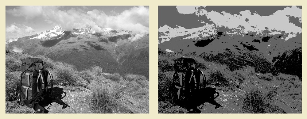
Let's use a field to make the negative of a photograph. Here's the code (its so short, we don't even need a draw() routine):
import AULib.*;
void setup() {
  PImage Img = loadImage("BruceBeach.jpg");
  size(Img.width, Img.height);
  image(Img, 0, 0);                                  // draw the photo
  AUField field = new AUField(this, width, height);  // make the field
  field.fromPixels(AUField.FIELD_LUM);               // read pixels into field
  for (int y=0; y<field.h; y++) {
    for (int x=0; x<field.w; x++) {
      float v = field.z[y][x];  // get the gray value at (x,y)
      field.z[y][x] = 255-v;    // replace it with the inverse
    }
  }
  field.toPixels(0, 0);     // copy the field to the screen
}
Here are the results. The starting photo is an image I shot on Bruce Beach in New Zealand, in a random microsecond when the flies weren't feasting on me.
AUMultiField
Fields are only able to hold a single value, but color pictures typically have three channels, one each for red, green, and blue. Of course, you can represent and work with a color picture by creating three fields, one for each channel. Rather than manage three independent objects on your own, use an AUMultiField.
This object holds as many fields as you like. There are some special-purpose routines to help you out when you want to treat the first 3 fields in an AUMultiField as red, green, and blue. An AUMultiField is very similar to an AUField, with a few changes to accommodate the fact that the data is now held in three channels rather than just one. So I'll go through these pretty fast, assuming you're already familiar with AUField calls.
Note that an AUMultiField can hold RGB pictures in 3 layers, or RGBA pictures (that is, with alpha) in 4 layers. So some of these calls have two versions, one each for RGB and RGBA, depending on what kind of information you want to put in and take out. The field doesn't keep track of what it's holding; that's entirely up to you. So you can put weather data into the first field, stock market data into the second, and so on, and then copy that information to the screen as colors. The library will just read the numbers from each field and do its job. Do note that if you're thinking of your fields as holding color values (including A, or alpha) then they should be in the range [0, 255].
Note for graphics pros: You may be familiar with the idea of pre-multiplied alpha when storing color values. Its a wonderful technique, but Processing doesn't use it. To avoid endless confusion, I don't use it here either. In an AUMultiField, pixels are stored "straight", and not pre-multiplied by their alpha values.
Creating
You create an AUMultiField much like an AUField. Provide a pointer to your sketch (the keyword this), followed by the number of fields you want, the width, and height:
AUMultiField( PApplet app, int numFields, int wid, int hgt);
You can create an AUMultiField with any positive number of fields that you want. Make sure you make it with all the fields you'll need, though, since you can't add more once the object has been built.
Here's how to create a new AUMultiField that has 6 layers, each the same size as your graphics window:
AUMultiField myField = new AUMultiField(this, 6, width, height);
Your new AUMultiField starts out with a value of 0 at every location.
Like an AUField, you can reach in and mess with the data. Here are the internal fields:
- int w: the width (read-only; don't assign to this variable!)
- int h: the height (read-only; don't assign to this variable!)
- AUField[] fields: an array of AUField objects (change this all you like)
Important! Read this! Just as with an AUField, do not change w or h! They're made available because its incredibly convenient, but never write new values into them.
If you're storing a color picture, then the first three entries in the fields array are for red, then green, then blue. So for example, the green value at entry x=2, y=6 is written
myField.fields[1].z[6][2]
If you choose to store an alpha value along with color (discussed more below), then that is presumed to be in the fourth field (index 3). So the alpha value for the above pixel could be set with
myField.fields[3].z[6][2] = 128; // set alpha to 50%
Reading and Writing
You can fill up an AUMultiField from onscreen pixels or an offscreen buffer (that is, a PGraphics object), just like an AUField , and you can go the other way, too. There's no valueType necessary, because we arent converting color to gray values. You can choose whether you want to save each pixels RGB values in the first three fields, or the RGBA values in the first four.
void RGBfromPixels();
void RGBAfromPixels();
void RGBfromPixels(PGraphics pg);
void RGBAfromPixels(PGraphics pg);
Writing is a bit more interesting, because we have more choices. First, we can choose whether we want to write RGB values from the first three fields, or RGBA values from the first four. If we write RGBA, then the alpha value in the fourth field will act as expected, giving the pre-existing screen color when alpha is 0, to the fields RGB color when alpha is 255, and intermediate blends for intermediate values. Remember that the value of alpha, like all fields, is floating-point.
void RGBtoPixels(float dx, float dy);
void RGBAtoPixels(float dx, float dy);
Sometimes using an alpha value in the fourth field is inconvenient, and you'd rather draw your values of alpha from another, independent AUField . Then this new field acts exactly like the mask from the AUField section. In other words, supplying a mask does exactly the same job as using RGBAtoPixels() above, but it lets you get the alpha values from an external variable, rather than an internal field.
As with an AUField , the upper-left corner of the mask is presumed to align with the upper-left corner of the color data. Use the second version of the call to offset the mask (this ability makes an external mask a little more flexible than using RGBAtoPixels() above):
void RGBtoPixels(float dx, float dy, AUField mask);
void RGBtoPixels(float dx, float dy, AUField mask, float mx, float my);
As with an AUField, there are versions of each of these calls for writing into a PGraphics object, rather than the screen:
Flattening
If you have at least 3 fields, you can treat the first 3 as colors and set them all at once:. You can assign the same value to every RGB or RGBA entry in every field:
void flattenRGB(float fr, float fg, float fb);
void flattenRGBA(float fr, float fg, float fb, float fa);
You can set all the pixels of all the fields in your AUMultiField at once to the same value:
void flatten(float v);
You can just set all the pixels of any specific field to the same value:
void flattenField(int fieldNumber, float v);
Setting and Getting Multiple Values
You will usually assign values directly into the fields array. But a lot of things come in triples (e.g. colors and 3D points) and quads (e.g., colors with alpha, and homogeneous 3D points). So there are conveniences for setting the first three or four fields at once:
void setTriple(int x, int y, float v0, float v1, float v2);
void setQuad(int x, int y, float v0, float v1, float v2, float v3);
If you're using your AUMultiField to store colors (either RGB in the first three fields, or RGBA in the first four), there are some convenience routines to save you some time and effort when converting to and from Processing's color type.
You can set the first three fields with RGB values, or the first four with RGBA values, with
void RGBAsetColor(int x, int y, color c);
void RGBsetColor(int x, int y, color c);
Going the other way, you can get back a color if you have at least 3 (or 4) fields:
color getRGBAColor(int x, int y);
color getRGBColor(int x, int y);
Scaling the Range
You can scale your color image in two ways.
Scaling separate means that each color channel is individually scaled. That is, the library finds the minimum and maximum red values, and then scales all the red values to fill the range you've provided. Then it does the same thing for green, and then blue. This ensures that each color channel fills the entire range, but it can change the composite colors you see on the screen, because the RGB values are usually not being scaled by the same amount. This can be useful when you're working with abstract data, but if your data is a picture of some kind, it can make it look weird.
Scaling together means the library finds the smallest and largest values in all the channels at once, and then scales all three channels by those same values into your range. Thus you're guaranteed that at least one color in at least one pixel will have the largest value you specify, and and at least one color in at least one pixel will have the smallest value you specify. If you're manipulating color images, this is usually the choice you want.
There are two calls for each type of range-setting. If you want to scale all the fields in your object, use these:
void setRangeTogether(float zmin, float zmax);
void setRangeSeparate(float zmin, float zmax);
If instead you want to only affect the first few fields, these variations will only work with fields numbered 0 to numFields, leaving the rest alone:
void setRangeTogether(float zmin, float zmax, int numFields);
void setRangeSeparate(float zmin, float zmax, int numFields);
Frequently we want our new scale to be [0,1]. To save you a little typing, there are shortcuts for that. These correspond to the four calls above, but merely set zmin to 0 and zmax to 1 for you:
void normalizeTogether(int numFields);
void normalizeSeparate(int numFields);
void normalizeTogether();
void normalizeSeparate();
Similarly, when working with colors we often our new scale to be [0,255]. These calls scale the first three fields to [0,255]:
void normalizeRGBTogether();
void normalizeRGBSeparate();
And these scale the first four fields to [0,255]:
void normalizeRGBATogether();
void normalizeRGBASeparate();
Arithmetic
You can add a fixed value to every entry in every field:
void add(float val);
You can multiply every entry in every field by a given value:
void mul(float val);
You can restrict these to a single specific field if you like:
void addField(int fieldNumber, float val);
void mulField(int fieldNumber, float val);
As usual, there are shortcuts if you have at least 3 fields to store RGB values:
void RGBadd(float fr, float fg, float fb);
void RGBmul(float mr, float mg, float mb);
Or if you have at least 4 fields to store RGBA values:
void RGBAadd(float fr, float fg, float fb, float fa);
void RGBAmul(float mr, float mg, float mb, float ma);
As with AUField objects, you can also combine one AUMultiField with another by adding or multiplying them element by element:
void add(AUMultiField mf);
void mul(AUMultiField mf);
Copies and Duplicates
You can copy one AUMultiField to another, as long as the're of the same size (if the widths, heights, or number of fields are different, you get an error message and otherwise nothing happens). To copy your AUMultiField into a destination, hand that target to your original:
void copy(AUMultiField dst);
You can also create a brand-new, independent duplicate of any AUMultiField :
AUMultiField dupe();
Copying and Swapping Layers
You can easily copy one field to another with
void copyFieldToField(int from, int to);
If you want to copy several successive fields at once, use
void copySeveralFields(int from, int to, int n);
This will copy field from to field to , then ( from+1 ) to ( to+1 ), and so on, n times. This is particularly useful for copying color images, where you use n=3 .
The two ranges can overlap. That is, you can say something like this:
myMultiField.copySeveralFields(3, 4, 3);
and when you're done, the starting contents of field 3 will be in field 4, the starting contents of field 4 will be in field 5, the starting contents of field 5 will be in field 6. In other words, the routine won't over-write data you're trying to copy until its been successfully copied.
Similar routines exist for swapping either one or several fields. To exchange all the contents of fields a and b, call
void swapFields(int a, int b);
If you want to swap several consecutive clusters of fields, call
void swapSeveralFields(int a, int b, int n);
This will swap field a with field b , then ( a+1 ) with (b +1 ), and so on, n times.
Composition
You can compose one color AUMultiField over another using the standard Porter-Duff over operator:
void over(AUMultiField B);
This will compose the calling field over B , and modify B to hold the result. If B has only three fields it will be presumed to have an alpha value of 1 everywhere. If B has a fourth field, that field will be used for B s alpha, and will be updated along with B s first three color fields to correctly hold the composite alpha.
If the calling field doesn't have a fourth field for alpha, or you would prefer to use a mask, just provide the mask (the alpha values will come from the mask even if the calling field has an alpha field).
void over(AUMultiField B, AUField mask);
(Note for graphics folks: as I mentioned before, the library does not use pre-multiplied alpha. The results of over are straight, or non-premultiplied, values).
AUMultiField Examples
Let's use our example from the AUField discussion and modify it to use an AUMultiField . Once again, we don't need a draw() routine.
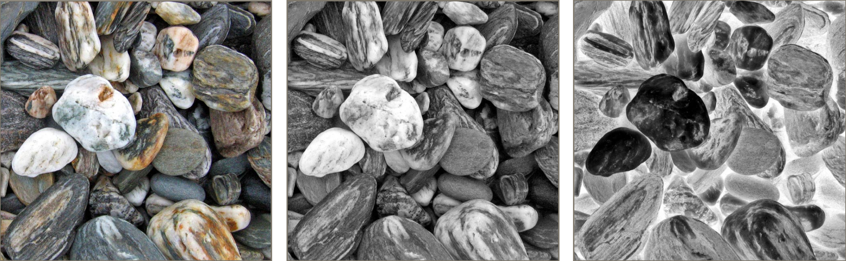
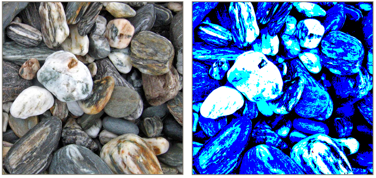
Just for fun, I'll do a little bit of goofy thresholding. I'll look at the red, green, and blue values independently. If the red is above 192, I'll set it to 255, otherwise 0. I'll do the same thing for green, using 128, and blue, using 64. The result is that we see lots of blue, lots of regions of blue and green (cyan), and lots of red, green, and blue (white).
void setup() {
  PImage Img = loadImage("07-28-Bruce-Beach-3a.jpg");
  size(Img.width, Img.height);
  AUMultiField mf = new AUMultiField(this, 3, width, height);
  image(Img, 0, 0);
  mf.RGBfromPixels();
  for (int y=0; y<mf.h; y++) {
    for (int x=0; x<mf.w; x++) {
      float redVal = mf.fields[0].z[y][x];
      float grnVal = mf.fields[1].z[y][x];
      float bluVal = mf.fields[2].z[y][x];
      mf.fields[0].z[y][x] = (redVal > 192) ? 255 : 0;
      mf.fields[1].z[y][x] = (grnVal > 128) ? 255 : 0;
      mf.fields[2].z[y][x] = (bluVal >  64) ? 255 : 0;
    }
  }
  mf.RGBtoPixels(0, 0);
}
Here are the results:
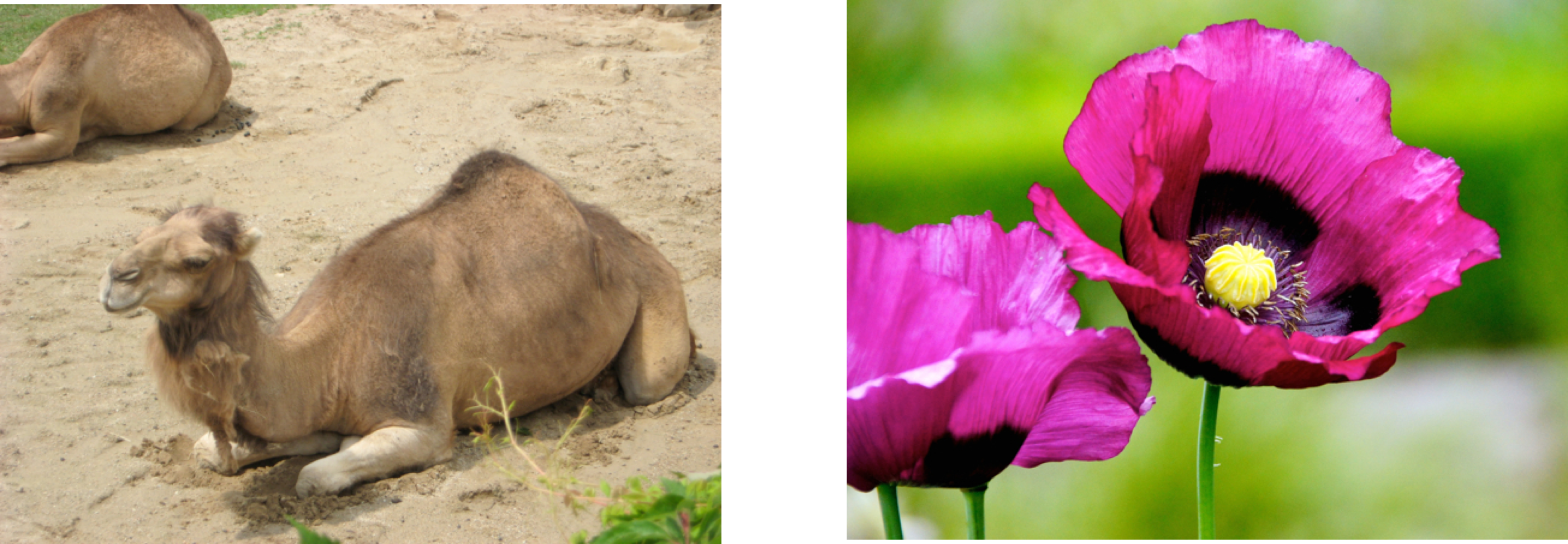
Here's another example. In this code, I'll create two AUMultiField objects. The first, called camel, will hold a picture of a camel in 4 layers, enough for RGBA. The second, flower, will hold an picture of a flower in 3 layers, or just RGB. I'll use Processing's noise() function to fill up the fourth field of camel with either 0 or 255. Then I'll use over() to draw camel (with its transparency in the fourth field) over flower (which is by default opaque everywhere, since it doesn't have any alpha values). The result is that the camel covers up the flower where its alpha channel is 255, and otherwise leaves it alone.
Here are my two source pictures (both from freeimages.com. To keep the code simple, I cropped them so they both had the same dimensions.
Here's the result of their noisy mix:
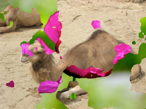
Of course, since I'm using noise, every run of the program will produce a different image. Here's the program:
import AULib.*;

void setup() {
  size(600, 450); // both pictures are 600 by 450
  AUMultiField camel = new AUMultiField(this, 4, width, height);  // RGBA
  AUMultiField flower = new AUMultiField(this, 3, width, height); // RGB

  // draw the flower and save it in RGB form
  PImage flowerImage = loadImage("Flower.jpg");
  image(flowerImage, 0, 0);
  flower.RGBfromPixels();

  // draw the camel and save it in RGB form. We'll add alpha next.
  PImage camelImage = loadImage("camel.jpg");
  image(camelImage, 0, 0);
  camel.RGBfromPixels();

  // fill up the alpha channel in camel with 255 or 0
  float noiseScale = .01; // chosen by trial and error to look good
  for (int y=0; y<height; y++) {
    for (int x=0; x<width; x++) {
      float v = noise(x*noiseScale, y*noiseScale); // get noisy value [0,1]
      camel.fields[3].z[y][x] = v > .5 ? 255 : 0;  // save either 0 or 255
    }
  }

  // image composition: flower = camel over flower
  camel.over(flower);

  // and draw Flower to the screen
  flower.RGBtoPixels(0, 0);
}
Cameras and Motion Blur
Now were going to shift gears, and prepare for the second topic in this note: cameras. We begin by talking about an important effect called motion blur.
When we photograph a fast-moving object in the real world, the object can appear streaky, or blurry, in the final image
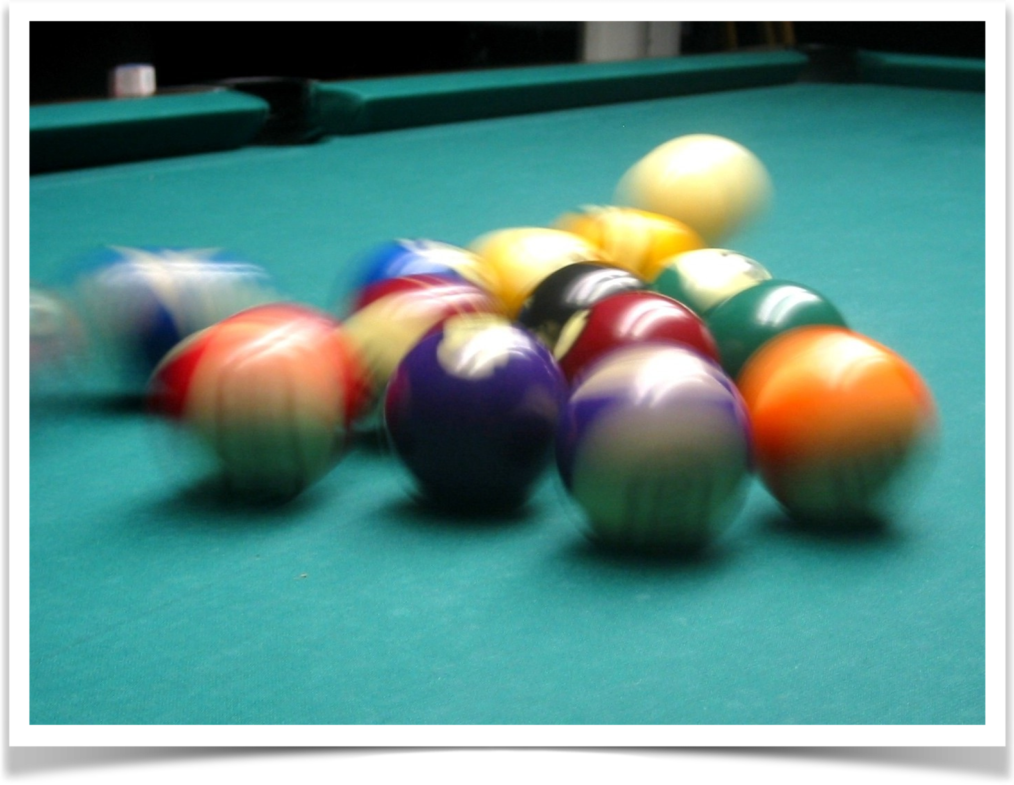
Notice that these moving balls arent just blurred in an indiscriminate sense. Rather, the're leaving behind very specific trails that reveal their motion.
Where are these blurs coming from? The key is to think about the structure of a camera. Here's an illustration of a very simple box camera.
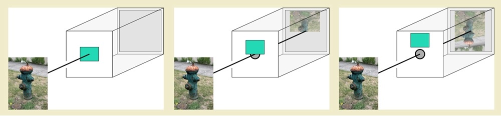
In this minimal camera, there's an opening, or iris, to admit light, which then falls on a sheet of film (or more commonly today, an electronic sensor). Just behind the iris there's a shutter, which blocks the incoming light until you want to take a picture. When the shutter is blocking the iris, the inside of the camera is pitch black, and the film is recording no light. We say the shutter is closed.
Then you push the button on the camera, the shutter moves out of the way, or opens, and light goes through the iris onto the film. After a moment the shutter drops into place again, stopping the flow of light. Notice that it takes some time for the shutter to open and then close again. If objects move when the shutter is open, then the film records the light coming from them as they move, creating blur.
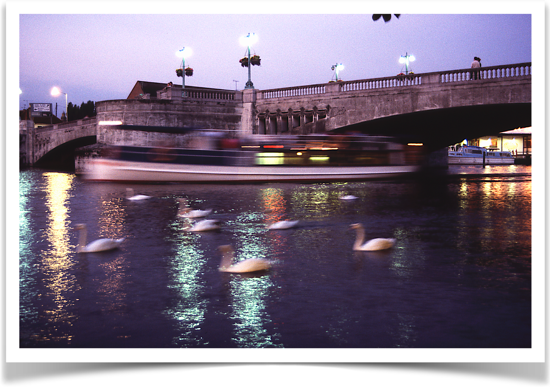
In this image, the camera was held still for a few moments. The nearby swans swam by, moving from right to left, leaving short trails behind them. The boat in the distance also traveled from right to left, but it was moving much faster, and so left behind a much longer trail. The length of any motion blur trail depends on both the apparent speed of the objects, and the length of time that the shutter is open.
Motion blur is often caused by moving objects, but it can be caused by a moving camera as well. All that matters is that an object appears to be moving across the plane of the film, regardless of the relative motions of objects and camera that produced that motion.
Generally speaking, the faster the object or the longer the exposure, the longer the trail. Also note that long trails are often dimmer than short ones, because the object is moving faster across the film and thus is contributing less light to each location in the film.
We see motion blur in every movie and television show. Our visual systems have been extensively trained to understand it as a cue that tells us things are moving. Weve come to expect it, in fact to demand it. If we see a video or film of something moving, and the motion blur isn't there, it feels wrong somehow.
To see this, watch an old monster movie. The monsters were animated by posing them and taking a picture, then moving them slightly and taking another picture, over and over. There's no motion blur, because the models were fixed in place when the image was taken. As a result, the motion seems off somehow. It might feel jittery or shaky to you, as though the monster is moving in small lurches, or you might not even have words for it, but there's something not right.
When we create animations with the computer, its important that fast-moving objects leave behind some of this characteristic motion blur, or our audience will perceive it like the old movie monsters: it feels jerky and wrong.
You can read a lot more about motion blur, and see some crazy images that you can make with weird shutters, in my May 1999 column of Andrew Glassner's Notebook in IEEE Computer Graphics & Applications. (you can also find it online on my personal website at www.glassner.com; choose "CGA Columns").
The AUCamera object in my library is designed to make it easy to create animations that contain motion blur. The basic idea is that you render multiple images for each frame of output. So for example if a ball is moving left to right over the course of a frame, you'd create several images as the ball moves, and hand them to the camera. It then combines them, using a shutter shape of your choice, to create a final frame. The camera then saves that frame for you. So all you have to do is produce your images and hand them to the camera, which then does all the work.
Of course, the camera has a bunch of options and controls, and you can dig into them and fine-tune how things work if the defaults arent what you want.
For clarity, I'll call each image you produce a snapshot and the composite image produced by the camera (and saved to disk) a frame. So your draw() routine produces images, or snapshots, and hands them to the camera, which combines them with the shutter to produce a frame.
Note that unlike most of the other tools in the AU library, the AUCamera object is not meant for real-time imaging. That's because it builds up your final frames by assembling multiple snapshots that you draw into your graphics window, so your users see the frames being built. This tool is really intended for making frames of animation that you'll later put together in an animated gif or video for display.
Shutters
There are lots of different shutters in the real world. In this library, there are two shutters that you'll probably use the most, and a few others for fun. If you'd rather use your own shutter, you can do that, too.
To demonstrate the action of each shutter, I'll present the results of three different little animations, each involving four circles.
The first scene shows two circles moving down, and two others moving up, as shown below. Note that these circles are covering far, far more distance in the space of a single frame than you would ever typically want in a real animation. But for the purposes of demonstration, I've chosen these big motions so that the effects of the different shutters are easy to see.
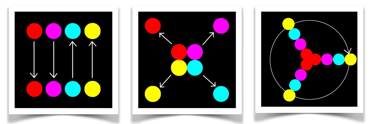
The middle and right diagrams show the radial case, where the disks move outward, and the circular case, where the balls spin in a full circle clockwise, starting and ending again at 3 oclock.
In the rendered examples below, the circular images usually came out pretty dark, because the disks are covering a lot of territory in a short time. This makes their trails on any given frame pretty eim. To make them easier to read I brightened them up in Photoshop. The other scenes are untouched.
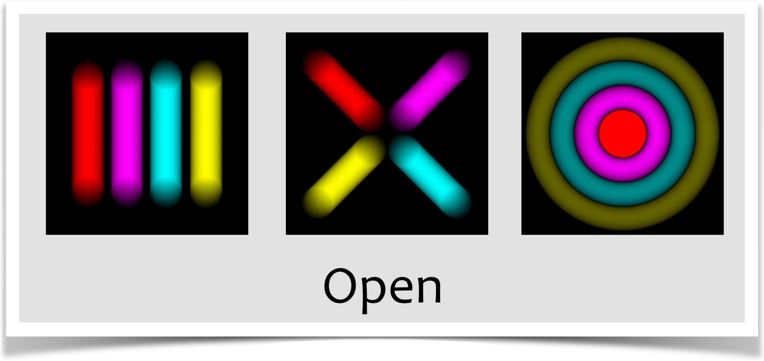
The Open Shutter
The first built-in shutter is the open shutter. You specify it with shutter type SHUTTER_OPEN. This is a perfect shutter, or perhaps even a non-shutter. It opens instantly and completely at the start of the exposure, and remains fully open until the end.
In practice, this means that the final frame is simply the average of all the subimages.
The image below shows the results for our three test cases, created with the open shutter. These pictures make sense: the're just the average of all the snapshots. The ends of the straight trails are faint because the disks don't spend much time there, and the're bright where the balls are overlapping on themselves, exposing the film to a lot of color. Remember, the right-most image (for the circular case) has been brightened up in Photoshop so it would be bright enough to read clearly.
Remember that in these frames, the balls are moving much, much farther than they would probably ever move in a real animation. In practice, the motion blur trails are usually pretty short, like in the figure above. But these exaggerated motions make it easy to see what the camera and shutter are producing.
The open shutter has been used by countless people for decades to make movies with reasonable motion blur. The shutter isn't an accurate model of any real-world mechanism, but it does a surprisingly good job of creating good-looking motion blur.
Besides looking good, the open shutter runs the fastest of all the shutters in the library. For these reasons, this is the default shutter. And its probably the only one you'll ever need.
The Uniform Shutter
There may be times when the open shutter doesn't work for you, and you want something a little more physically motivated.
In that case, you can move on to the uniform shutter. You specify it with shutter type SHUTTER_UNIFORM. Here we pretend that the shutter is a piece of material whose opacity we can control. Think of it stretched over the film, so when its opaque the film is in complete darkness. When we start the exposure, the uniform shutter gradually becomes increasingly transparent everywhere at once. It finally becomes completely transparent, and stays that way for a while. Then it becomes opaque again, and the exposure is complete.
This raises the question of how the opacity should over time. All of the shutters in the AU library use the same timing curve: it starts at 0, climbs up and smoothly curves to 1, stays there, then smoothly drops down to 0 again, all over the course of a single exposure. Each of the shutters (except the open shutter above) has a single parameter controlling it, and this curve drives that parameter over the course of each exposure. We'll see below how to control the shape of this curve. For now, here's the general shape:
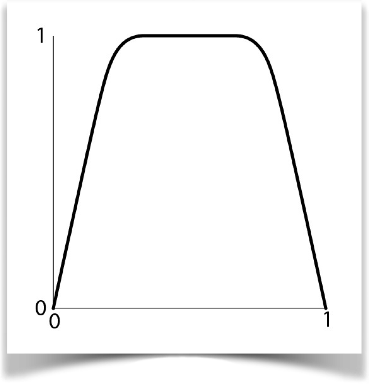
When we use this curve to control the opacity of the uniform shutter, 0 means fully opaque and 1 means fully transparent. So the shutter start out opaque, then the whole thing smoothly turns transparent, it stays that way, then becomes opaque again.
Here are the results for our three test cases
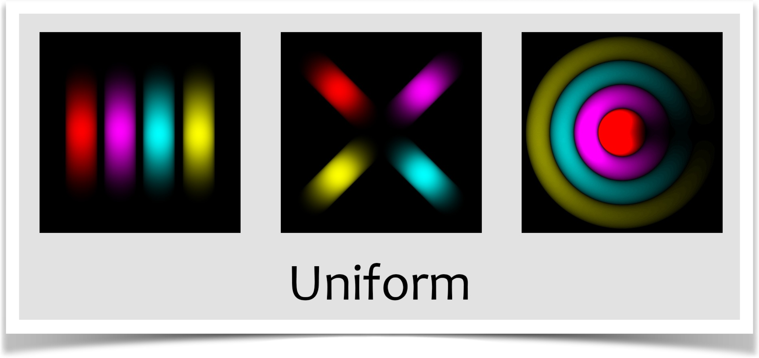
Generally speaking, these are a lot like the open shutter, but the paths seem shorter at both ends. That makes sense, as the shutter is opaque at the start and end of the frame.
This is a bit more realistic than the open shutter, and in cases where the open shutter doesn't look right, this will almost always do the job for you. Your sketch will take a very little bit longer to produce frames, because the uniform shutter is slightly slower than the open shutter.
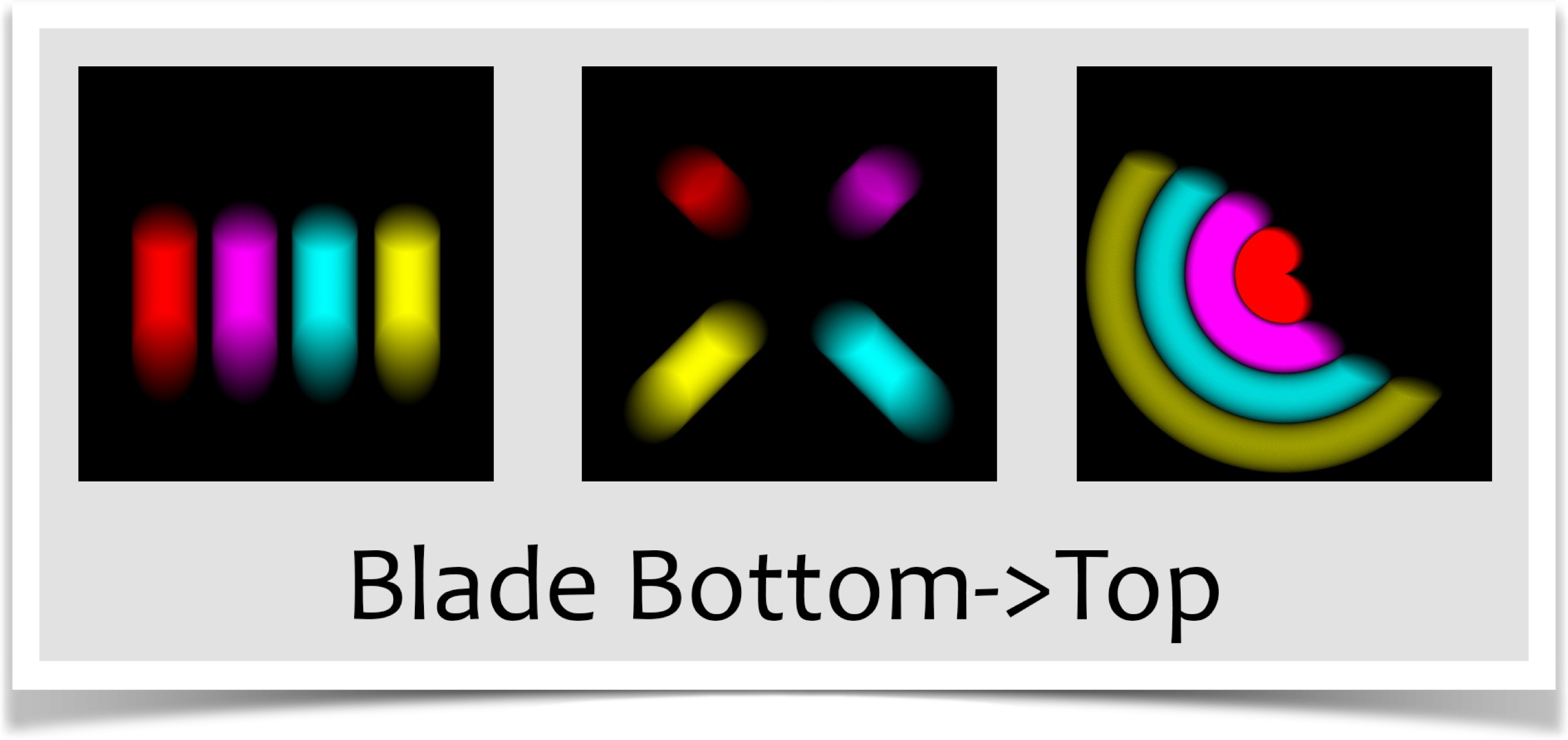
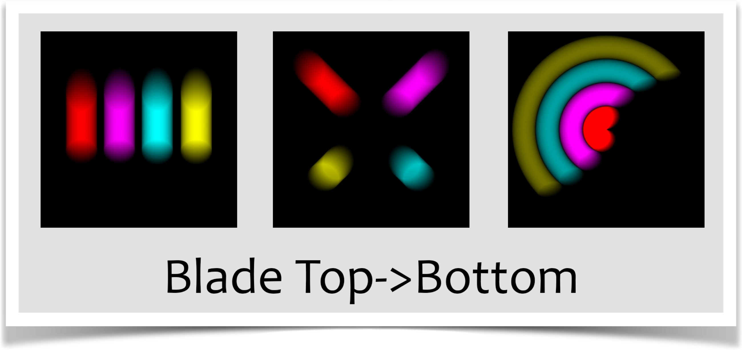
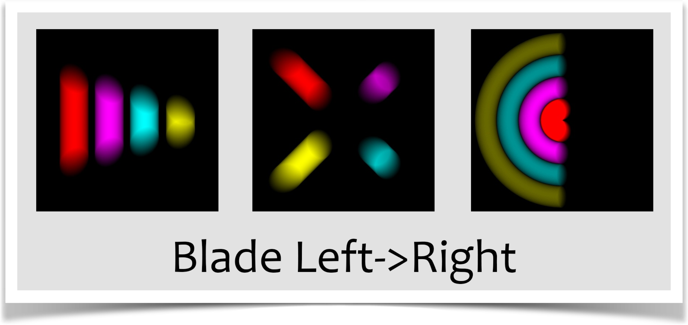
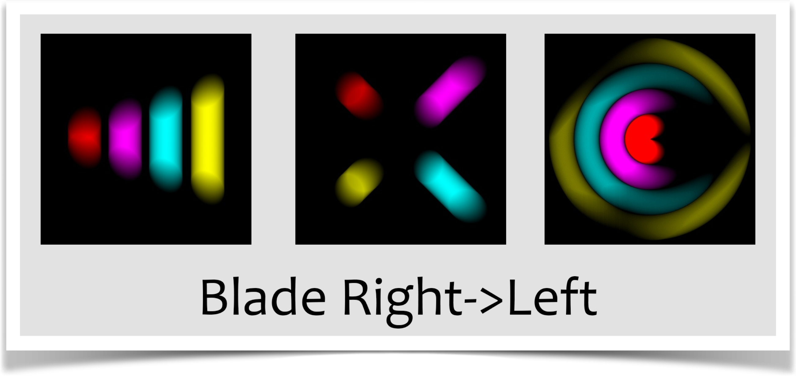
The Blade Shutter
Although the open shutter will probably satisfy 99% of your needs, and the uniform shutter will handle the other 1%, neither of these is particularly realistic. We have a computer here, why not offer some more realistic choices, just for the fun of it? I think that's a good-enough reason, so this section and the next offer a couple of shutters that are modeled on real physical devices.
Probably the simplest realistic shutter is called the guillotine , or blade , shutter. You specify it with shutter type SHUTTER_BLADE with two more letters that identify which way it's moving (we'll see those below). You can probably guess how it works. The figure below shows the idea. A piece of opaque material sits in front of the iris. To start the exposure, it slides out of the way, and stays there for a while, before sliding back to end the exposure.
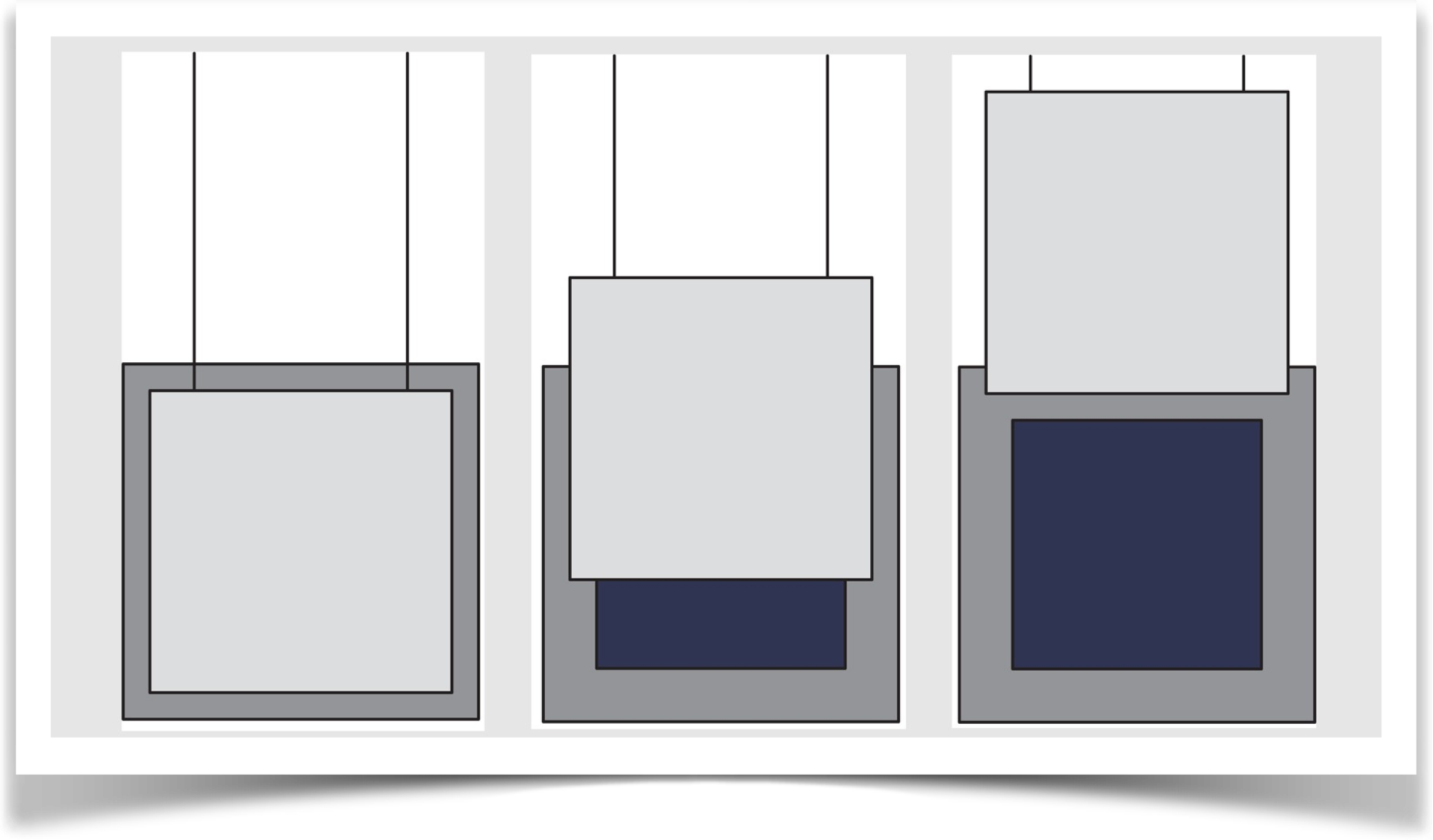
As you might imagine, we can slide the blade shutter in any direction to get it to reveal the iris. Depending on whats happening in your scene, this can change the shape of the blur that's captured, because different parts of the film are exposed at different times.
I've implemented the blade shutter moving in four directions: moving up, down, right, and left. I'll repeat their formal names here:
- SHUTTER_BLADE_UP
- SHUTTER_BLADE_DOWN
- SHUTTER_BLADE_RIGHT
- SHUTTER_BLADE_LEFT
In practice, you'd probably never notice the difference between these. But in our test scenes with very exaggerated motions, you can see the differences. Try to picture in your head why these different shutters produce these similar, but different, results.
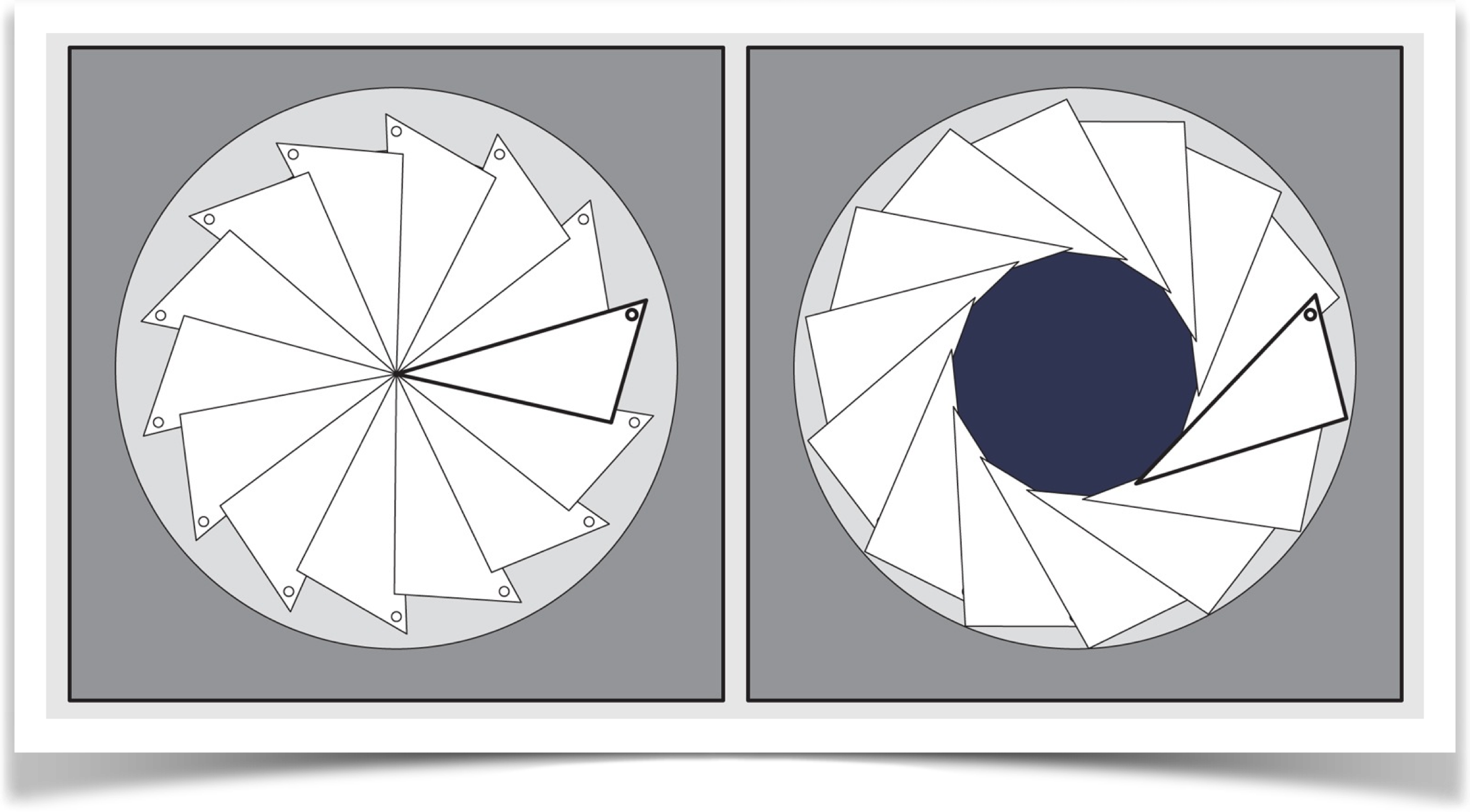
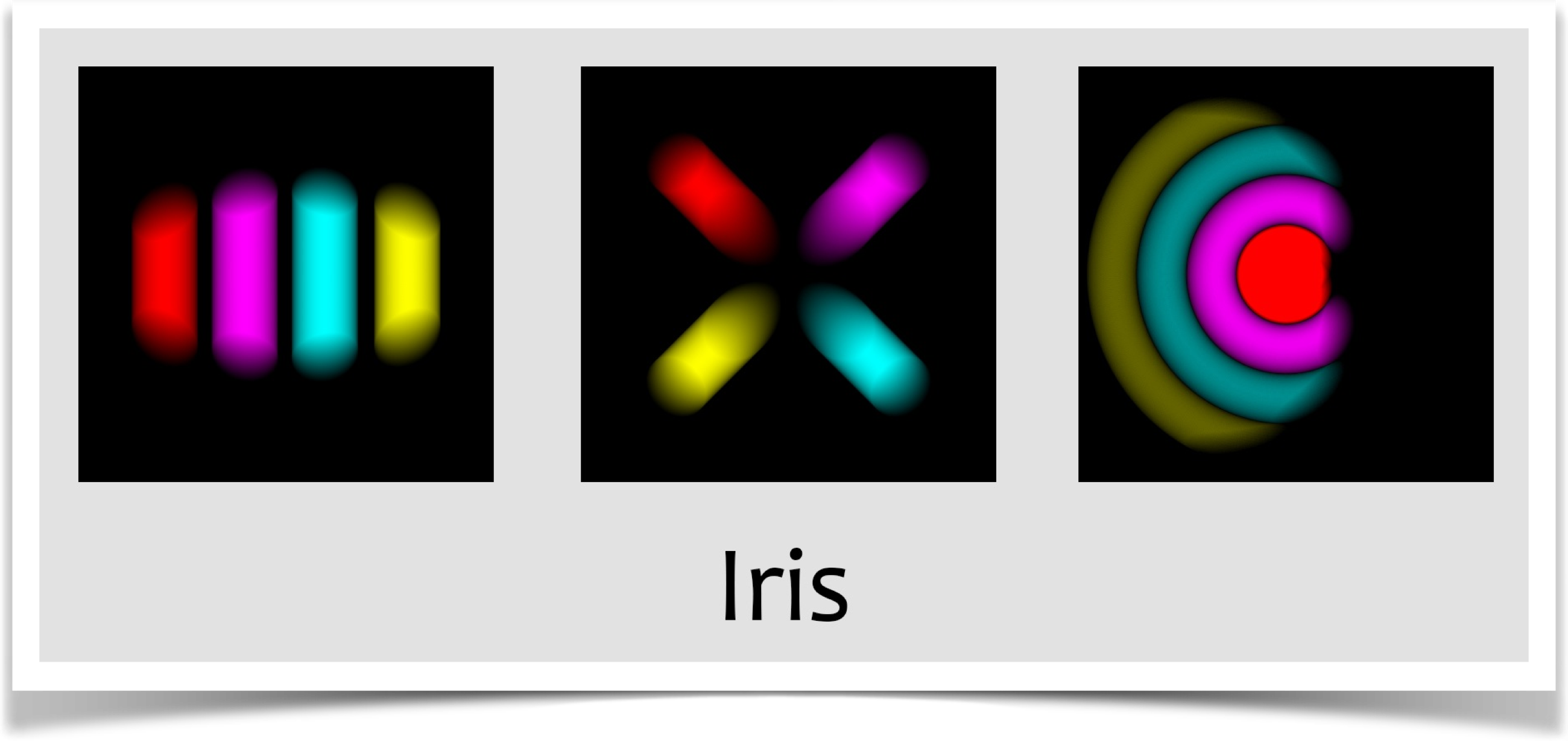
The Iris Shutter
The iris shutter is also physically motivated. You specify it with shutter type SHUTTER_IRIS. This shutter is modeled after the mechanism found in many older cameras. A ring of metallic plates moves in unison to open up an ever-enlarging approximate circle, until the entire iris is exposed. Then the rings close again, shrinking the circle until the iris is fully covered. The figures show the geometry, and then the results.
The AUCamera
The AUCamera object packs up all the logic involved in maintaining a camera, merging in new frames as masked by a shutter, and saving the results. If you like the defaults, you only need three lines in your code. If you want finer control, its available.
Creation
You create a camera by giving it a pointer to your sketch (just use the keyword this), followed by how many frames your animation will run, how many subframes (or exposures) you're going to produce per frame, and whether or not the library should automatically save output files (its useful to turn this feature off when debugging):
AUCamera(PApplet app, int frameCount, int exposureCount, boolean saveFrames);
For example,
AUCamera MyCamera;
MyCamera = new AUCamera(this, numFrames, numExposures, true);
You'll probably make your camera (here, MyCamera) a global variable declared near the top of your sketch. The line to call the constructor will probably be in your setup(). Because the camera initializes itself to the graphics windows size, its important that you always create your camera after calling size().
To use the camera, just tell it to take an exposure at the end of every draw():
That's the whole thing (some complete examples appear below). By default, the camera will use an open shutter. Also by default, it will create a subfolder named pngFrames in your sketch folder. Inside that subfolder, it will store files named frame00000.png, frame00001.png, and so on, each holding one motion-blurred frame. When its saved the number of frames you specified in numFrames, the camera tells Processing to exit, and your program ends.
Then you can read your files into any movie-editing program and assemble them into a movie file. Or you can convert them to gif and use them to make an animated gif (note that I don't recommend saving gif directly, as the gif encoder used by Processing is known to be buggy. Save your images in png format, then convert them to gif using one of the many free format-converting tools).
Choosing Your Shutter
The most common customization is to choose your own shutter. You do so by calling the method setShutterType() with one argument:
void setShutterType(int shutterType);
Choose shutterType from this list. The blades are labeled by the direction they move at the start of the exposure. For example, SHUTTER_BLADE_RIGHT moves to the right, stays there for a while, then moves back to the left to complete the exposure.
- SHUTTER_OPEN
- SHUTTER_UNIFORM
- SHUTTER_BLADE_RIGHT
- SHUTTER_BLADE_LEFT
- SHUTTER_BLADE_DOWN
- SHUTTER_BLADE_UP
- SHUTTER_IRIS
AUCamera Options
You can choose to fine-tune many aspects of the cameras behavior after you've created it. Some of these override the values you give when you create the camera. I don't recommend doing that, but sometimes it's useful.
Set the number of frames to save.
void setNumFrames(int numFrames);
Set the number of exposures in each frame.
void setNumExposures(int numExposures);
Scale each frame to (0,255) using the AUMultiField together method (see above).
void setAutoNormalize(boolean autoNormalize);
(default = false)
Specify whether or not you want the camera to save frames as the're made.
void setAutoSave(boolean autoSave);
(default = true)
Specify if you want your program to exit after the last frame is saved.
void setAutoExit(boolean autoExit);
(default = true)
Set the file format for frames: gif, tif, tga, or jpg (do not include a period).
void setSaveFormat(String saveFormat);
(default = png)
Set the path in your sketch's directory where frames are to be saved.
void setSavePath(String savePath);
(default = pngFrames)
When you initially create your camera, you might set saveFrames to false while you're developing or debugging your code. This means the camera won't automatically exit when the last frame is collected, and time will just keep rolling on. By default, the value returned by getTime() will wrap from 1 back to 0. If you set timeWrap to false , then the value returned by getTime() will simply increase. Note that this does not affect the value returned by getFrameTime().
void setTimeWrap(boolean timeWrap);
(default = true)
Some animations build on pre-existing images. If you want to generate a bunch of exposures before saving, set this value to the number of exposures you want. These pre-exposures do not have to create full frames.
void setPreRoll(int preRoll);
(default = 0)
The remaining two options let you shape the curve that controls how the shutters change over time. Generally each shutter has a closed form (where its blocking the iris completely) and an open form (where the iris is fully exposed). Over the course of a single frame, it goes from closed to open, stays open, then closes again. The speed with which this happens is defined by a symmetrical curve that runs from 0 (at the start of the frame) to 1 (at the end). The value of the curve also runs from 0 to 1.
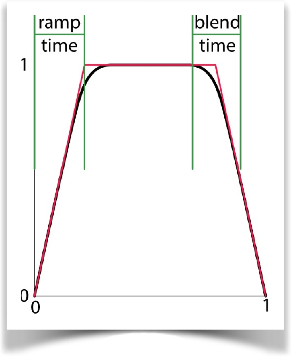
The ramp time is the fraction from 0 to 1 that identifies where the ramp would end if there was no smoothing. In the timing curve, that's where the red line reaches the value of 1. The blend time is the fraction of the ramp time over which smoothing occurs (note that this is not a fraction of the total exposure, like the ramp time. Its a fraction of the ramp time, from 0 to 1).
For example, suppose we have the defaults of a ramp time of 0.2, and a blend time of 0.25. Then the blend time is 0.25*0.2 = 0.05. So we have a smooth rise from 0 in the interval (0, 0.15), a blend up to 1 from (0.15, 0.25), a value of 1 from there to (0.75), then a blend back down from 1 in the interval (0.75, 0.85), and finally a ramp down until 0.
The curve controls one parameter for each shutter type. Here's how:
- SHUTTER_OPEN: no effect
- SHUTTER_UNIFORM: opacity (0=opaque, 1=transparent)
- SHUTTER_BLADE_RIGHT: position moving right (0=closed, 1=open)
- SHUTTER_BLADE_LEFT: position moving left
- SHUTTER_BLADE_DOWN: position moving down
- SHUTTER_BLADE_UP: position moving up
- SHUTTER_IRIS: size of circle (0=closed, 1=open)
To set these times, you can use these routines after you've created your camera.
void setRampTime(float rampTime);
(default = 0.2)
You can also set the blend time.
void setBlendtime(float blendTime);
(default = 0.25)
Getting the Time
Because your draw() routine is just creating images, its often useful to ask the camera where it is in the frame-making process. You can get this information in two different forms by asking the camera for the current time. In both cases, the time you get back represents the time at the start of the next snapshot. Thus before you've saved any snapshots, the time is 0.
The first form of the time, called simply time, runs from 0 towards 1 over the course of your animation. I say towards 1 because it never quite hits 1. That's because if you're making a cyclic animation, which is very common, you don't want the last frame to be identical to the first, or your animation would have a little stutter at that point.
To get the time, call getTime():
float getTime();
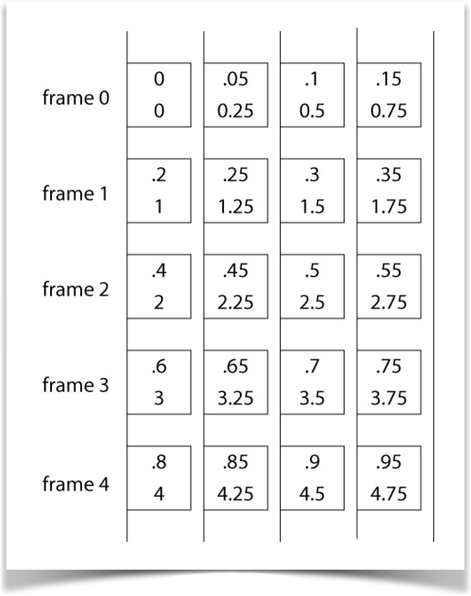
The second form of time, called frame time, gives you a floating-point number, where the integer part tells you which frame your next snapshot will contribute to, and the fractional part identifies how far into that frame the snapshot is located. For example, if you had 5 snapshots per frame, and a frame time of 3.4, you know the next time you call expose() you'll be saving the third snapshot of frame 3 (because with 5 snapshots, they will be at 3.0, 3.2, 3.4, 3.6, and 3.8).
To get the frame time, call getFrameTime():
float getFrameTime();
If you're debugging (discussed in the next section), the camera will keep going past the number of frames you want in your final animation. In other words, the time returned by getTime() will exceed 1. By default when the time exceeds 1 it will wrap back around to 0. To prevent this wraparound, call setTimeWrap(false) . Note that this setting does not affect the value returned by getFrameTime() , which never wraps.
The figure below shows the setup visually. Each box is a snapshot. The numbers show whats returned by the system before you call expose() for that frame. The upper value is that returned by getTime() , the lower value is whats returned by getFrameTime().
You can use whichever form of time is most convenient for your animation.
Debugging
You always need to call expose() at the end of draw() to keep the camera synchronized to your animation. But when you're debugging, you usually don't want the camera saving frames to disk (it slows things down without any value to you). You also usually want the camera to just keep cranking out times forever; you don't want it to exit when you've generated a specific number of frames. Its also common to want only one exposure per frame, so that things move along quickly and you can watch whats happening.
To get the camera to do all three of these things (don't save frames, generate one exposure per frame, and keep running past the end of the animation), set saveFrames in the constructor to false.
Remember to set saveFrames back to true when you're done and ready to save your frames.
Occasionally you really want to have multiple exposures per frame even when debugging, call setNumExposures() after creating the camera to set the exposure count.
Another way to debug is to call expose() with the optional argument false:
Camera.expose(false);
If you're exposing an image that would cause a frame to be saved, then that frame will not be saved. This lets you suppress individual frames. Be sure to take out the false when you're finished debugging!
Custom Shutters
You can make your own shutters. The technique is to fill up an AUField with values that indicate how opaque each pixel should be for that exposure. You then hand that field to the camera, which gets the pixels from the screen as usual, but uses your AUField object as the shutter rather than one of the built-in shutters. At each pixel, it finds the corresponding value in your AUField , and it multiplies the pixels RGB values by that number. So to make a shutter opaque at a given pixel, put a value of 0 in the corresponding field entry. To make it transparent, put a value of 1 in there. And of course intermediate values will result in intermediate opacities.
To make an exposure using a custom shutter, call
void exposeWithShutter(AUField customShutter);
For example, you might write a routine called makeMyShutter() that takes as input the current time, and returns a field representing the shutter at that moment. You could then control the camera this way:
float time = MyCamera.getTime();
AUField myShutter = makeMyShutter(time);
MyCamera.exposeWithShutter(myShutter);
When you supply your own shutter, the values of rampTime and bladeTime are ignored. In all other ways, the camera operates as usual.
A Comment About Moving Shutters
As I mentioned earlier, for casual animations the open shutter is probably your best bet: its simple and its the fastest. If you want something a little more controllable, use the uniform shutter.
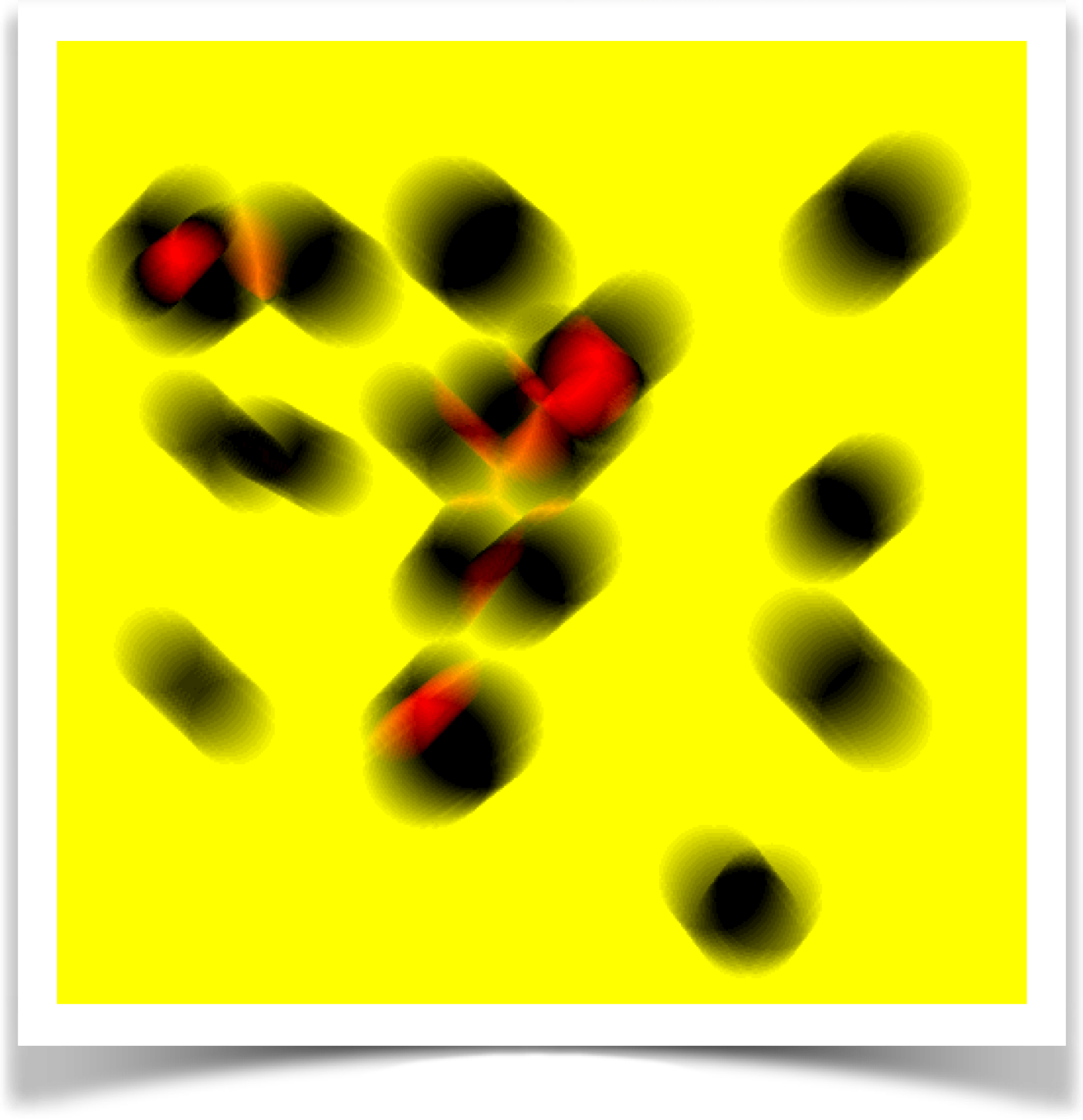
If you do want to use the blade or iris shutters, or custom shutters of your own, a word of advice: make sure that you use enough snapshots! Time things out (with a combination of numExposures and setRampTime() ) so that your shutter moves only a pixel or two from one snapshot to the next. If you don't use enough snapshots, you can get various weird and unpleasant-looking artifacts in your frames, as shown in this example.
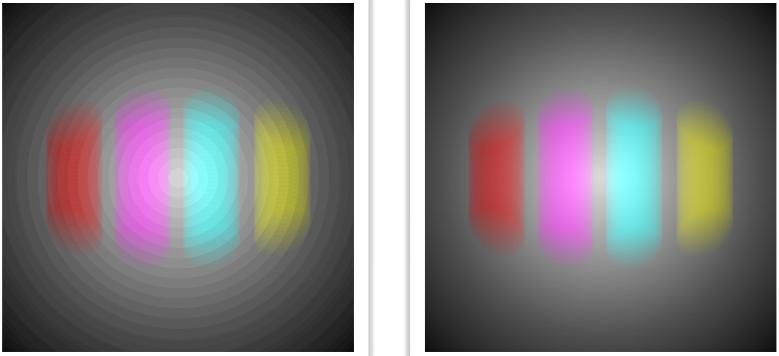
The figure above shows an example of such a problem, created with an iris shutter and our vertical test scene (though I changed the background to a medium gray). The interesting thing here is that nothing is going wrong: as the iris gets bigger (and then smaller) by a whole bunch of pixels on every snapshot, then the picture on the left is a faithful image of what were drawing. The same thing can show up with the blade shutters. And if you use your own custom shutters, all kinds of artifacts can occur.
The trick to curing almost all of these problems is to to make sure yo'ure creating enough snapshots so that the shutter is moving by only a pixel or two each time.
This advice doesn't apply to the open or uniform shutters, since they don't move.
Examples
Here's an example to create a movie of a disk moving in a circle. This is the entire program, soup to nuts.:
import AULib.*;

AUCamera MyCamera;     // make my camera object
int NumFrames = 8;     // number of frames in this animation
int NumExposures = 50; // exposures per frame
void setup() {
  size(500, 500);
  MyCamera = new AUCamera(this, NumFrames, NumExposures, true);
}

void draw() {
  background(0);
  fill(255, 0, 0);                             // fill with red
  float theta = MyCamera.getTime() * TWO_PI;   // angle around the circle
  float cx = (width/2.) + (180 * cos(theta));  // circle center x
  float cy = (height/2.) + (180 * sin(theta)); // circle center y
  ellipse(cx, cy, 100, 100);                   // draw the circle
  MyCamera.expose();                           // save this exposure
}
Notice that we don't have to build up the frames ourselves, save them, or exit when were done. The camera does all of that for us! We just make images and expose them.
Here are the 8 frames of the result (read the top row left to right, then the bottom row left to right):
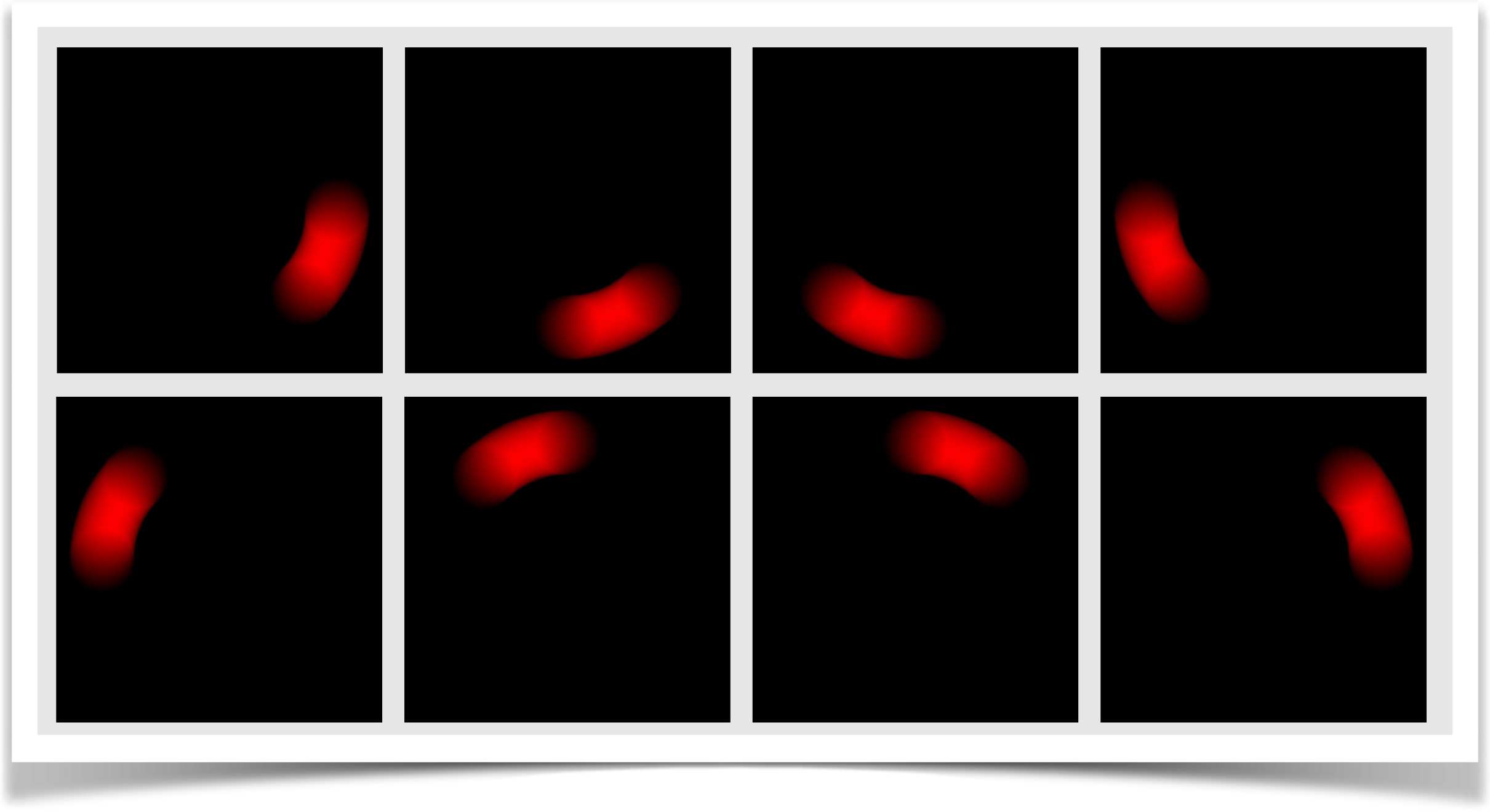
This example used all the defaults, including an open shutter. Even though the ball is moving incredibly fast, if you put this together as a little gif animation, it looks pretty good!
For fun, lets change up some of the options and regenerate the frames. I'll only change setup() , and leave draw() untouched:
void setup() {
  size(500, 500);
  MyCamera = new AUCamera(this, NumFrames, NumExposures, true);
  MyCamera.setShutterType(AUCamera.SHUTTER_UNIFORM);
  MyCamera.setRampTime(0.4);
  MyCamera.setSaveFormat("tif");
  MyCamera.setSavePath("tifframes");
}
So now were using a uniform shutter, it takes 40% of the frames total duration to fully open and another 40% to get closed (so its only fully open for the central 20% of the exposure), and I've set the output format to TIF. The change in shutter gives us similar, but different result:
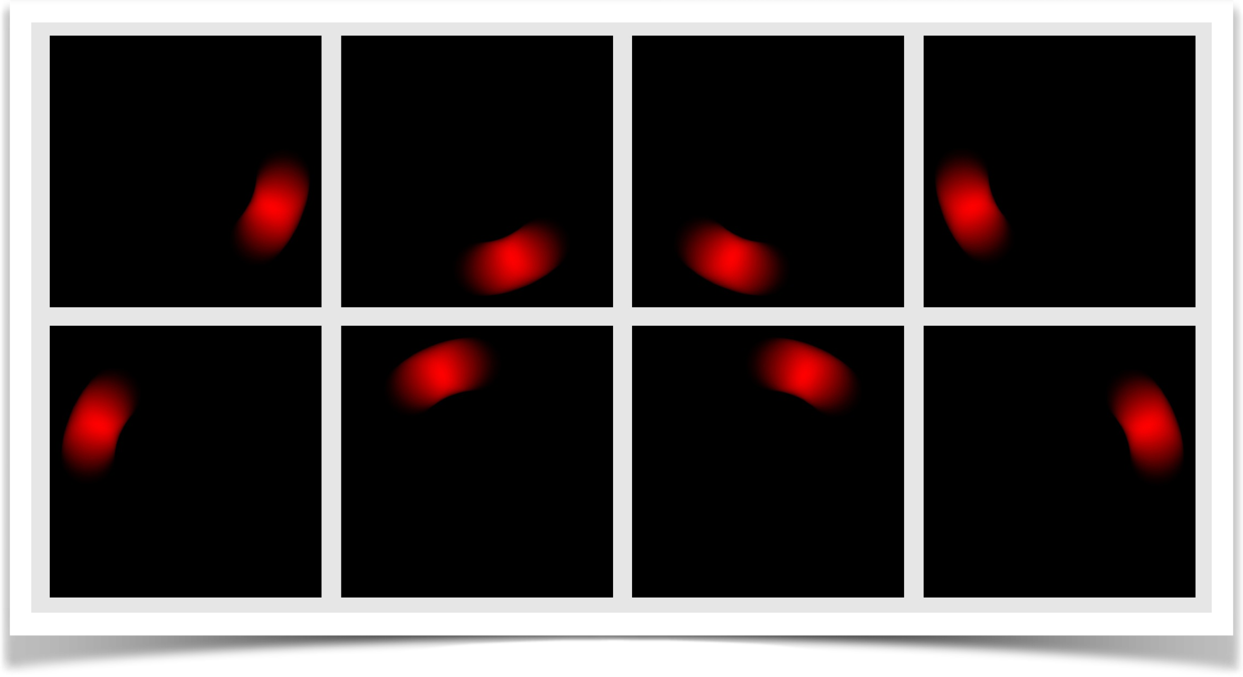
Notice that the trails are just a little bit shorter than for the open shutter. If you make animations out of either of these sets of frames, they both look great, as though you were looking at frames of a real object moving quickly.
Let's switch gears now. This example uses all three objects in this tech note: an AUField , an AUMultiField , and an AUCamera . The idea is that we create a bunch of randomly-sized circles floating around the screen and bouncing off the edges. We want to highlight where they overlap, and of course everything should be motion-blurred.
The codes comments can probably guide you through what's happening, but here's a short overview. Each circle is an instance of a class called Disk , which holds the circle's center, radius, and per-frame motion in x and y. Each time I render a circle, I then add its motion to its center, and reverse its motion (and move it appropriately) if it bounces off any side of the window.
The interesting stuff happens when we draw a snapshot. Each circle is drawn into a PGraphics object as a white disk on a black background then I put that into an AUMultiField and add that to another AUMultiField that starts out as transparent black. When I'm done drawing, I go through that AUMultiField pixel by pixel, assigning yellow to background pixels and red to overlaps (since I don't do anything where there's just one circle, they appear as black). Then I call the cameras expose() to take a snapshot. The motion isn't cyclic, so the animation doesn't form a loop, but it looks pretty cool.
import AULib.*;

class Disk {
  float cx, cy, r, dx, dy; // center, radius, and per-frame motion
  Disk() {
    r = random(30, 60);              // pick a radius
    cx = random(2*r, width-(2*r));   // pick a starting point
    cy = random(2*r, height-(2*r));
    dx = random(1, 2);               // horizontal speed
    if (AULib.flip()) dx = -dx;      // half the time, move left
    dy = random(1, 2);               // vertical speed
    if (AULib.flip()) dy = -dy;      // half the time, move up
  }
  void renderAndUpdate(PGraphics pg) {
    pg.fill(255);                       // draw a white circle
    pg.ellipse(cx, cy, 2*r, 2*r);
    cx += dx;                           // move horizontally
    if ((cx-r < 0) || (cx+r > width)) {
      dx = -dx; cx += 2*dx;             // bounce off left and right
	}
    cy += dy;                           // move verticaly
    if ((cy-r < 0) || (cy+r > height)) {
      dy = -dy; cy += 2*dy;             // bounce off top and bottom
    }
  }
}
Disk[] DiskList;         // the disks we're drawing
AUMultiField Buildup;    // the accumulating image
AUMultiField OneCircle;  // picture of a single circle
AUCamera Camera;         // the camera

void setup() {
  size(500, 500);
  DiskList = new Disk[20];           // create a bunch of random disks
  for (int i=0; i<DiskList.length; i++) {
    DiskList[i] = new Disk();
  }

  // create the screen and camera objects
  Buildup = new AUMultiField(this, 3, width, height);    // only needs RGB
  OneCircle = new AUMultiField(this, 4, width, height);  // this has RGBA
  Camera = new AUCamera(this, 8, 20, true);   // 8 frames of 20 snapshots each
}

void draw() {
  Buildup.flattenRGB(0, 0, 0);  // the image we're building starts out black

  PGraphics pg = createGraphics(width, height);
  for (int i=0; i<DiskList.length; i++) {
    pg.beginDraw();
    pg.background(0, 0, 0, 0);          // draw on a transparent black field
      DiskList[i].renderAndUpdate(pg);  // draw this disk
    pg.endDraw();
    OneCircle.RGBAfromPixels(pg);       // load with the PGraphics RGBA
    Buildup.add(OneCircle);             // add with transparency to accumulator
  }

  background(0);  // background is black
  loadPixels();
  for (int y=0; y<height; y++) {
    for (int x=0; x<width; x++) {
      // set empty pixels to yellow, and overlaps to red
      int index = (y*width)+x;
      if (Buildup.fields[0].z[y][x] < 1) pixels[index] = color(255, 255, 0);
      if (Buildup.fields[0].z[y][x] > 255) pixels[index] = color(255, 0, 0);
    }
  }
  updatePixels();   // draw the new pixels
  Camera.expose();  // and take an exposure
}
Here are the frames we get back. As usual, I chose pretty extreme colors so that the images would be easier to read. Notice that the red zones that show the overlaps between the balls are being motion-blurred properly.
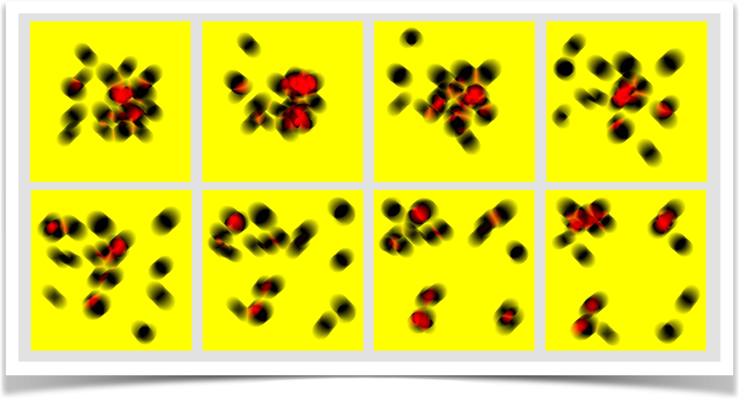
Even though I once again had everything moving fast for the purposes of making clear examples, if you put these frames together into an animated gif they look pretty good!
Its interesting to consider that you can sometimes fake motion blur if all your objects are things you can draw explicitly. For example, to fake the motion blur of a circle you could draw lots of faint circles one on top of the other along the motion path. I've done this myself to make a quick fake trail behind an object.
Unfortunately, this technique often fails, producing bad-looking images. The problem is closely related to the problem from drawing many copies of a faint image produced a badly quantized, or posterized, result. The same thing can easily happen if you're drawing shapes rather than images, leading to trails that look posterized and weird.
Another common problem involves creating fading trails by painting over your whole scene with a box that's set to a translucent version of your background color. The idea is that by drawing this on top of every frame, each pixel that hasnt been written to recently will slowly disappear by turning into the background color. But again, because the system is working with colors that are quantized to values from 0 to 255, this technique often results in old pixels never completely fading away, but always holding a bit of color from your old images. So your trails never really fade away, they just get dimmer and then get stuck at a very dim level.
The AUCamera uses AUField and AUMultiField objects, storing everything as a floating-point number, so we avoid those problems. And it naturally motion-blurs everything correctly. Consider if you were faking the blurs by drawing lots of circles. How would you fake the blurs of the overlapping red zones? You could do it with a whole lot of programming, but it would take a lot of work and would be incredibly special-purpose code. Building frames from snapshots means everything blurs correctly, and you don't have to spend any time or effort even thinking about the issue. That's definitely a better way to work!
Motion blur is a wonderful way to improve the feel of animations, particularly when objects are moving a lot. You don't need to use it on every animation, but when its this easy to include, why not?
Resources
The library, examples, documentation, and download links are all at the Imaginary Institutes resources page:
https://www.imaginary-institute.com/resources.php
To use it in a sketch, remember to include the library in your program by putting
import AULib.*;
at the top of your code. You can put it there by choosing Sketch>Import Library... and then choosing Andrew's Utilities, or you can type it yourself.
This document describes only section of the AU library, which offers many other features. For an overview of the entire library, see Imaginary Institute Technical Note 3, The AU Library.